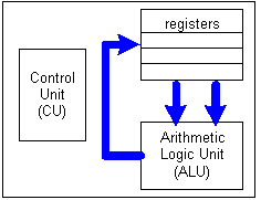
Figure 14.1: Central Processing Unit (CPU) subunits.
Any sufficiently advanced technology is indistinguishable from magic.
Arthur C. Clarke
John von Neumann draws attention to what seemed to him a contrast. He remarked that for simple mechanisms, it is often easier to describe how they work than what they do, while for more complicated mechanisms, it is usually the other way around.
Edsger Dijkstra
As was discussed in Chapter 1, virtually all modern computers have the same basic layout, known
as the von Neumann architecture. This layout divides the hardware of a computer into three main
components: memory, Central Processing Unit (CPU), and input/output devices. Memory provides
storage for data and program instructions. The CPU is in charge of fetching instructions and data
from memory, executing the instructions, and then storing the resulting values back in memory.
Input devices (such as the keyboard, mouse, and microphone) and output devices (such as the
screen, speakers, and printer) enable user interaction by allowing people to enter inputs and by
displaying data, instructions, and the results of computations.
This chapter explores the details of the von Neumann architecture by describing the inner workings of a computer. We develop our explanation incrementally, starting with a simple model of the CPU datapath and then adding main memory and a Control Unit. When combined with input and output devices, these components represent an accurate (albeit simplified) model of a modern, programmable computer. Software simulators (originally developed by Grant Braught at Dickinson College) are provided for each model to facilitate experimentation and hands-on learning.
As we saw in Chapter 1, the CPU acts as the brain of the computer. It is responsible for obtaining data and instructions from memory, carrying out the instructions, and storing the results back in memory. The set of instructions that a particular computer's CPU can understand and execute is known as that computer's machine language. In Chapter 8, we explained that programmers can control a computer's behavior by defining instructions for its CPU- this is accomplished either by writing programs directly in machine language or by writing programs in a high-level language and then translating them into machine language. Even programs that exhibit complex behavior are specified to the CPU as sequences of simple machine-language instructions, each performing a task no more complicated than adding two numbers or copying data to a new location. However, the CPU can execute these instructions at such a high speed that complex programmatic behavior is achieved.
The CPU itself is comprised of several subunits, each playing a specific role in the processor's overall operation. These subunits are the Arithmetic Logic Unit (ALU), the registers, and the Control Unit.

Figure 14.1: Central Processing Unit (CPU) subunits.
The path that data follows within the CPU, traveling along buses from registers to the ALU and then back to registers, is known as the CPU datapath. All of the tasks performed by a computer, from formatting a document to displaying pages in a Web browser, are broken down into sequences of simple operations; the computer executes each individual operation by moving data from the registers to the ALU, performing computations on that data within the ALU, and then storing the result in the registers. A singe rotation around the CPU datapath is referred to as a CPU datapath cycle, or CPU cycle.
Recall that in Chapter 1, we defined CPU speed as measuring the number of instructions that a CPU can carry out in one second. Since each instruction requires a single CPU cycle to execute, CPU speed directly corresponds to the number of CPU cycles that occur per second. For example, an 800-MHz CPU is able to perform 800 million CPU cycles in a single second, whereas a 1.4-GHz CPU is able to perform 1.4 billion CPU cycles in a single second. However, one cannot evaluate CPUs solely by comparing processor speeds. This is because two machine languages might divide the same task into different sets of instructions, and one set might be more efficient than the other. That is, one CPU might be able to complete a task in a single cycle, whereas another might require several cycles to complete the same task. In order to compare CPU performance, you must consider the instruction set for each CPU, as well as such factors as the number of registers and size of the buses that carry data between components.
To help you visualize the behavior of the CPU datapath, a simple simulator has been provided with the text. The CPU Datapath Simulator models a simple CPU containing four registers. Using this simulator, you can follow the progress of data as it traverses the CPU datapath, from registers to the ALU and back to registers. To keep things simple, we have avoided including an explicit Control Unit in this simulator. Instead, the user must serve as the Control Unit, selecting the input registers, ALU function, and output register by clicking the knob images.
Figures 14.2 through 14.5 demonstrate using the simulator to add two numbers together-a task that can be completed during a single CPU cycle.
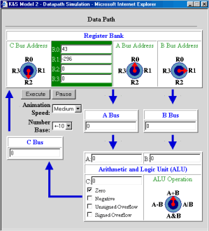
Figure 14.2: Initial settings of the simulator.
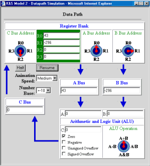
Figure 14.3: Data moving from registers to the ALU.
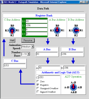
Figure 14.4: Data traveling from ALU to registers.
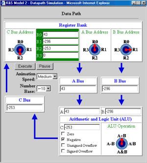
Figure 14.5: Final result of the CPU cycle.
Although the CPU datapath describes how a computer performs computations on data stored in registers, we have not yet explained how data gets into the registers in the first place and how the results of ALU operations are accessed outside the CPU. Both of these tasks involve connections between the CPU and main memory. As we learned in Chapter 1, all active programs and data are stored in the main memory of a computer. We can think of main memory as a large collection of memory locations, in which each location is accessible via an address. Similar to the way a street address (e.g., 27 Maple Drive) allows a mail carrier to find and access a mailbox, a memory address (e.g., memory location 27) allows the CPU to find and access a particular piece of main memory. A bus connects main memory with the CPU, enabling the computer to copy data and instructions into registers and then to copy the results of computations back to main memory. Figure 14.6 illustrates the interaction between a computer's main memory and CPU; the darker arrows represent the CPU datapath, whereas the lighter arrow represents the bus that connects main memory to the registers.
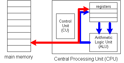
Figure 14.6: A bus connects Main Memory to the CPU.
As a program is executed, the Control Unit processes the program instructions and identifies which data values are needed to carry out the specified tasks. The desired values are then fetched from main memory along the main memory bus, loaded into registers, and utilized in ALU operations.
As a concrete example, imagine that you had a file containing 1,000 numbers and needed to compute the sum of those numbers. The file could be loaded into main memory-for example, at memory locations 500 through 1499. Then, the Control Unit would carry out the following steps to add those numbers and store the resulting sum back in main memory.
Note that each number must be transferred into a register before it can be added to the sum. In practice, transferring data between main memory and the CPU occurs at a much slower speed than that of a CPU cycle. This is mainly due to the fact that the electrical signals must travel a greater distance-for example, from a separate RAM chip to the CPU chip. In the time it takes for data to traverse the main memory bus and reach the registers, several CPU cycles may actually occur. Modern processors compensate for this delay with special hardware that allows multiple instructions to be fetched at once. By fetching several instructions ahead, the processor can often move on to the next instruction and perform useful computations while the previous data transfer is in progress.
To help you visualize the relationship between the CPU and main memory, we have augmented the CPU DataPath Simulator so that it incorporates main memory. This extended simulator includes a main memory that can store up to 32 numbers, with addresses 0 through 31. A new bus, labeled the Main Memory Bus, connects the main memory to the CPU; this bus allows data to be copied from main memory to the registers, as well as enabling the results of ALU operations to be stored in main memory. As in our previous example, this version of the simulator does not contain an explicit Control Unit. The user must serve as the Control Unit, selecting the desired settings on the Main Memory Bus to control the data flow.
Figures 14.7 through 14.9 demonstrate using the simulator to add two numbers stored in main memory.
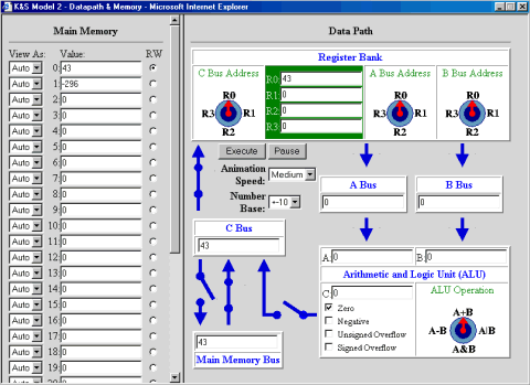
Figure 14.7: First, 43 is loaded from memory into R0.
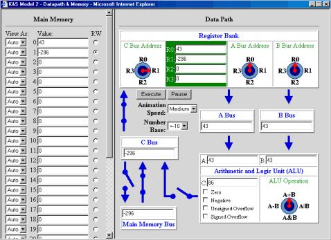
Figure 14.8: Second, -296 is loaded from main memory into R1.
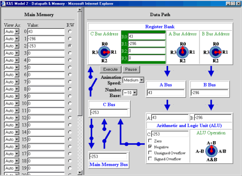
Figure 14.9: Finally, the values are added, and their sum is stored back in main
memory.
Two interesting observations can be made concerning the behavior of the simulator. First, the simulator requires more time to copy data between main memory and the CPU than it does to perform a CPU datapath cycle. This delay is meant to simulate the slower access times associated with main memory. In a real computer, as many as 10 CPU cycles might occur in the time it takes to transfer data between the CPU and main memory. The second observation is that, even while data is being fetched from main memory, operations are still performed on the CPU datapath. For example, in Figure 14.8, the number in R0 (43) is sent along both the A and B Buses to the ALU, yielding the sum 86. This might seem wasteful, since the result of the ALU operation is ignored (due to the disconnected C Bus). Surprisingly, this is an accurate reflection of a CPU's internal workings. It is more efficient for the CPU to perform needless computations while data is being transferred to or from main memory than it would be to add extra circuitry to recognize whether the C Bus was connected.
Now that we have discussed main memory, we are ready to focus on the last component of the CPU: a fully functioning, automatic Control Unit. To understand the role of the Control Unit, recall the tasks that you performed while using the simulators. When you experimented with the Datapath Simulator, you defined the computation that a CPU cycle would carry out by selecting the registers and ALU operation via knobs. In the datapath and main memory simulator, you controlled the flow of information between the datapath and main memory via switches on the buses. The key idea behind a stored-program computer is that tasks such as these can be represented as instructions, stored in main memory along with data, and then carried out by the Control Unit.
As we explained in Chapter 8, a machine language is a set of instructions corresponding to the basic tasks that a CPU can perform. In essence, each machine-language instruction specifies the configuration of hardware components that defines a particular computation within a CPU cycle. Thus, we could define machine-language instructions for our simulator by enumerating all the physical settings of knobs and switches. For example, the settings:
would define a configuration in which the contents of R0 and R1 are added and stored back in R2. This notation might suffice to control the behavior of a very simple machine, such as the one represented in our simulator; however, real-world CPUs contain an extremely large number of physical components, and specifying the status of all these parts during every CPU cycle would be impossible. Furthermore, since instructions are stored in memory along with data, the instructions must ultimately be represented as bit patterns.
Figure 14.10 describes a simple machine language that has been designed our simulator. Since the main memory locations in our simulator can hold a maximum of 16 bits, our language represents each instruction as a 16-bit pattern. The initial bits indicate the type of task that the CPU must perform, whereas the subsequent bits indicate the registers and/ or memory locations involved in the task. For example, all instructions that involve adding the contents of two registers begin with the bit pattern: 1010000100. The final six bits of the instruction represent in binary the destination register (i.e., the register where the result will be stored) and the source registers (i.e., the registers whose contents will be added by the ALU), respectively. For example, suppose that you wanted to add the contents of R0 and R1 and then store the result in R2-i.e., R2 = R0 + R1. The bit patterns for R2 (2 = 102), R0 (0 = 002), and R1 (1 = 012) would be appended to the initial bit pattern, yielding the machine-language instruction: 1010000100100001. Similarly, if the intent was R3 = R0 + R1, then the bit pattern for R3 (3 = 112) would replace that of R2: 1010000100110001.
| Operation | Machine-Language Instruction | Example |
|---|---|---|
| add contents of two registers, store result in another register
e.g., R0 = R1 + R2 | 1010000100 RR RR RR | 1010000100 00 01 10
will add contents of R1 (01) and R2 (10), store the result in R0 (00) |
| subtract contents of two registers, store result in another register
e.g., R0 = R1 - R2 | 1010001000 RR RR RR | 1010001000 00 01 10
will take contents of R1 (01), subtract R2 (10), and store the result in R0 (00) |
| load contents of memory location into register
e.g., R3 = M[5] | 100000010 RR MMMMM | 100000010 11 00101
will load contents of memory location 5 (00011) into R3 (11) |
| store contents of register into memory location
e.g., M[5] = R3 | 100000100 RR MMMMM | 100000100 11 00101
will store contents of memory location 7 (00101) into R3 (11) |
| move contents of one register into another register
e.g., R1 = R0 | 100100010000 RR RR | 100100010000 01 00
will move contents of R0 (00) into R1 (01) |
| halt the machine | 1111111111111111 |
The first two machine-language instructions in Figure 14.10 correspond to tasks that users can perform with the CPU Datapath simulator-i.e., selecting an ALU operation and the registers to be operated on within a CPU cycle. The next three instructions correspond to tasks that users can perform with the datapath and memory version of the simulator-i.e., controlling the flow of information between the main memory and the datapath. The last instruction, HALT, tells the Control Unit when a sequence of instructions terminates. Of course, a real CPU would require many more instructions than these. For example, if a CPU executes programs that include conditional statements (e.g., if statements and while loops), its machine language must provide branching instructions that allow the CPU to jump from one instruction to another. However, Figure 14.10's limited instruction set is sufficient to demonstrate the workings of a basic CPU and its Control Unit.
Once a uniform machine language for a particular CPU is established, instructions can be stored in main memory along with data. It is the job of the Control Unit to obtain each machine-language instruction from memory, interpret its meaning, carry out the specified CPU cycle, and then move on to the next instruction. Since instructions and data are both stored in the same memory, the Control Unit must be able to recognize where a sequence of instructions begins and ends. In real computers, this is usually controlled by the operating system, which maintains a list of each program in memory and its location. For simplicity, our simulator assumes that the first instruction is stored in memory location 0. The end of the instruction sequence is explicitly identified using the HALT bit pattern.
In order to track the execution of an instruction sequence, the Control Unit maintains a Program Counter (PC), which stores the address of the next instruction to be executed. Since we are assuming that all programs start at address 0, the PC's value is initialized to 0 before program execution begins. When the Control Unit needs to fetch and execute an instruction, it accesses the PC and then obtains the instruction stored in the corresponding memory location. After the Control Unit fetches the instruction, the PC is automatically incremented so that it identifies the next instruction in the sequence.
The steps carried out by the Control Unit can be defined as a general algorithm, in which instructions are repeatedly fetched and executed:
Fetch-Execute Algorithm carried out by the Control Unit:
- Initialize PC = 0.
- Fetch the instruction stored at memory location PC, and set PC = PC + 1.
- As long as the current instruction is not the HALT instruction:
- Decode the instruction - that is, determine the CPU hardware settings required to carry it out.
- Configure the CPU hardware to match the settings indicated in the instruction.
- Execute a CPU datapath cycle using those settings.
- When the cycle is complete, fetch the next instruction from memory location PC, and set PC = PC + 1.
For example, suppose that main memory contained the program and data shown in Figure 14.11.
|
|
The first five memory locations (addresses 0 through 4) contain machine-language instructions for adding two numbers and storing their sum back in memory. The numbers to be added are stored in memory locations 5 and 6. To execute this program, the Control Unit would carry out the following steps:
The Stored-Program Computer Simulator models the behavior of a complete, stored-program computer. Instructions and data can be entered into memory, with the first instruction assumed to be at memory location 0. The Control Unit is responsible for fetching and interpreting machine-language instructions, as well as carrying out the tasks specified by those instructions.
The simulator contains several display boxes to help users grasp the Control Unit's inner workings. As we described in the previous section, the Program Counter (PC) lists the address of the next instruction to be executed. In addition to the PC, CPUs also maintain an Instruction Register Register (IR), which lists the instruction that the Control Unit is currently executing. The IR is displayed in the simulator as an additional text box. Above these boxes, the simulator displays the actual knob and switch settings defined by the current instruction -this makes the correspondence between the machine-language instruction and the CPU hardware settings more obvious. Knob settings are specified as binary numbers: 00 represents a knob pointing straight up, 01 represents a knob pointing to the right, 10 represents a knob pointing down, and 11 represents a knob pointing to the left. Switch settings are written as bit patterns, with a 1 bit indicating a closed switch and a 0 bit indicating an open switch.
Figures 14.12 through 14.17 demonstrate using the simulator to execute the example machine-language program from Figure 14.11.
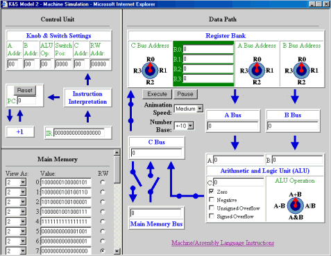
Figure 14.12: Initial state of the simulator, with program stored in main memory.
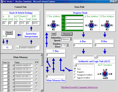
Figure 14.13: Simulator after the first instruction has been executed (R0 = MM5).
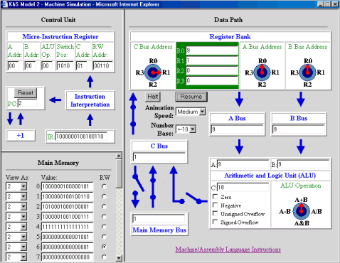
Figure 14.14: Simulator after the second instruction has been executed (R1 = MM6).

Figure 14.15: Simulator after the third instruction has been executed (R2 = R0 + R1).

Figure 14.16: Simulator after the fourth statement has been executed (MM7 = R2).

Figure 14.17: Simulator after the fifth statement has been executed (HALT).
The simulator is designed so that the user can enter values in main memory as either decimal or binary numbers. By default, values entered by the user are assumed to be decimal numbers. However, the user can always select 2 from the View As box to the left of a memory location in order to view the contents in binary. Before entering a machine-language instruction in a memory cell, the user must first select 2 from the View As box since machine-language instructions are represented in binary.
To complete our description of the stored-program computer, we must at least briefly discuss the role of input and output devices. Input devices such as keyboards, mice, and scanners allow the user to enter data and instructions into the computer, which are then stored in memory and accessed by the CPU. Likewise, output devices such as display screens, speakers, and printers allow the user to access the results of computations that are stored in memory.
On computers designed to run one program at a time, such as the first programmable computers in the 1950s and even the first personal computers in the 1970s, user interaction is direct and straightforward. The user enters program instructions and data directly into main memory locations using input devices such as keyboards or tape readers. Then, by flipping a switch or entering a specific command, the user instructs the CPU to fetch and execute the program instructions from memory. The user can then observe the results of the computation by displaying the contents of memory to a printer or display screen. This process is closely modeled by our simulator, in which the user directly enters instructions and data in main memory boxes, and then initiates execution by clicking a button. By contrast, most modern computers allow multiple programs to be loaded in memory and executed simultaneously. On such computers, the operating system must intercede, receiving the data and instructions from the user, storing them in memory, and providing the CPU with their locations.
Answers to be submitted to your instructor via email by Tuesday at 9 a.m.